LumenCon Lighting Control System
- Vadim Zhang
- Apr 16, 2017
- 4 min read

Updated: May 29, 2019
Practical Project: LumenCon Lighting Control System
Developer: LumenCon (Vadim Zhang, Birenkumar Patel, and Jinal Parmar)
Date of Initiation: January 22, 2017
Date of Completion: April 16, 2017
Contact: vadimzhz@gmail.com, 1001 Fanshawe College Blvd, London, ON
Short Summary
Contents
1. Introduction
2. Scope
3. Budget
4. Operational Overview
5. Conclusion
1. Introduction
LumenCon is a partnership of Fanshawe students created in order to plan, design, assemble, and program the Practical Project, which goal was a creation of a functioning prototype of an embedded system that controls indoor lighting. The Project’s objective was to produce a working electronic system on a breadboard that can save electrical energy for lighting and reduce the human effort for its manipulation.
Moreover, the system had to meet all the requirements included in a list of deliverables in a Project Scope, which specifies that the system must:
Sample occupancy and the degree of illuminance in a room.
Turn on or off the lights automatically and manually.
Modify brightness level of lighting automatically and manually.
Display this information on a terminal screen.
Consist of two nodes.
In the result, the functioning project was completed on time although it has a state of over budget with the CPI of 0.94.
The final prototype of one node of the Project assembled on a breadboard is demonstrated in Figure 1.

Figure 1. Project Prototype
2. Scope
The project involves planning and production of the smart lighting control system, which was finished as a functioning demonstrational prototype on a breadboard on April 14, 2017. The system is intended for automatic and manual regulation of the luminance of indoor lighting and for switching it on/off when the system detects/does not identify motion of a person.
A list of deliverables:
A functioning prototype that samples the occupancy and the degree of illuminance in a room.
The embedded system that modifies brightness level of lighting and regulates lights for turning on or off automatically.
Two lighting control nodes for two rooms that communicate with a terminal screen.
A screen where a current mode of operation and degree of illumination are displayed to the user.
A computer with the display that communicates with two nodes.
A working prototype for demonstration.
A System Schematic (Displayed in Figure 2) and a PCB design (Displayed in Figure 3).
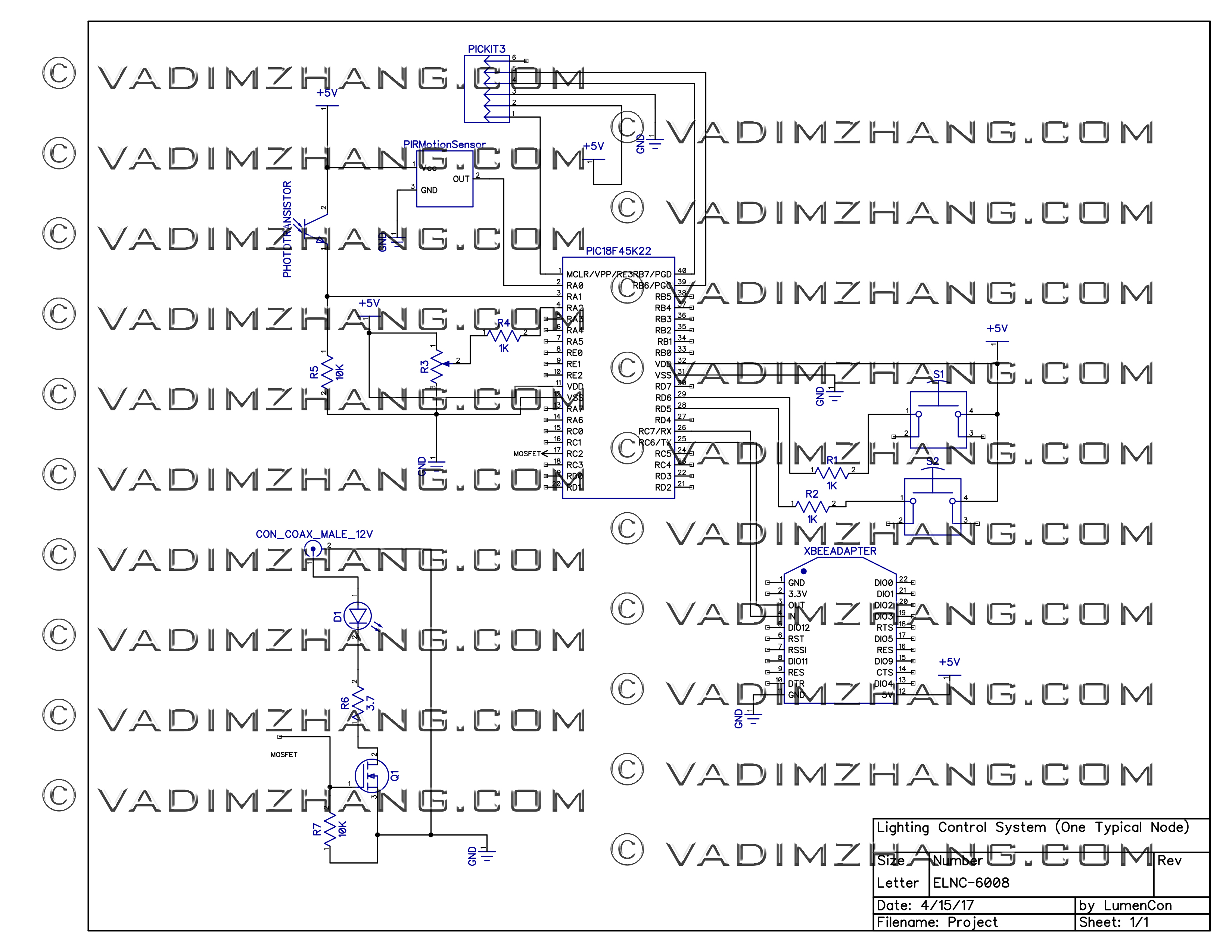
Figure 2. System Schematic
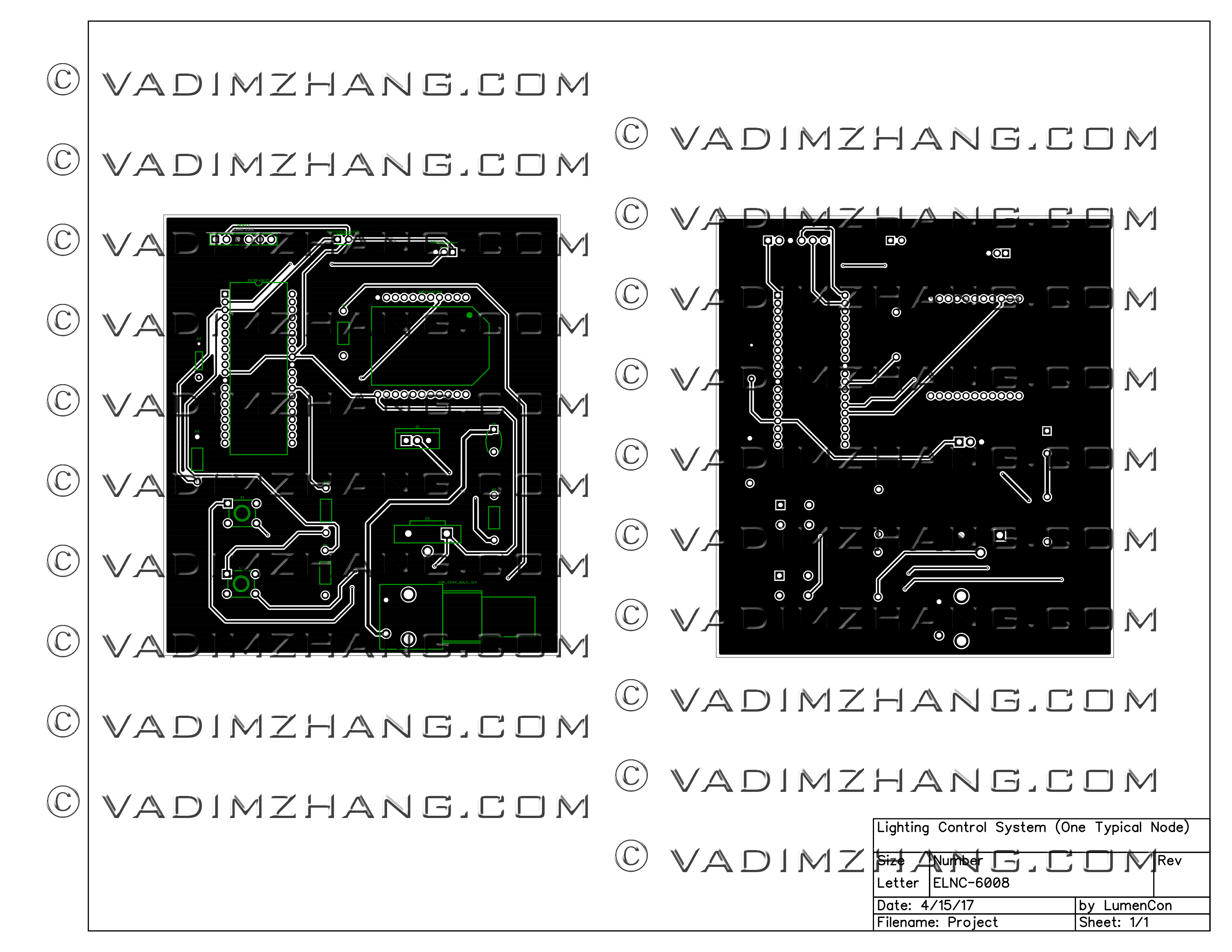
Figure 3. PCB Design
The project does not include:
A computer with the display that outputs information from two systems.
A terminal emulator program.
Software for managing a program code.
3. Budget
The comparison of estimated and actual costs of materials for the main tasks are included in Table 3.1.
Table 3.1. Budget Breakdown.

4. Operational Overview
There are two identical nodes of the system that can be located in different rooms, so the following description is related to one typical node. All the information about chosen modes and a degree light load’s brightness is transmitted wirelessly and displayed on a screen of a computer as it is shown in Figure 4. There are four operation modes of the system.

Figure 4. Displayed Information
Mode 1. Manual Mode. Turned ON
This is the default state of the system when it is powered that has functions of manual turning lights on or off and proportional regulation of their brightness. While pressing the push button 1 allows a user to select the manual or automatic mode, the push button 2 controls the LED’s state on or off. The intensity of lights from 0 to 300 lumen can be modified rotating the potentiometer.
Mode 2. Manual Mode. Turned OFF
The lighting can be turned on or off manually using the push button 2 only when the manual mode is selected. The intensity of the LED cannot be changed when it is switched off.
Video 1. Manual Mode Displayed
Mode 3. Automatic Mode. Turned ON
The push button 1 is intended for selection of the automatic mode, in which no more manual operation is required. The LED lights will turn on automatically if any motion is perceived by the PIR occupancy sensor that has a range up to 15 meters. The distance of sensitivity can be reduced to 5 meters turning an orange configuration screw on the motion sensor. During this mode, the system will automatically adjust the LED brightness depending on the degree of illuminance in a room.
Mode 4. Automatic Mode. Turned OFF
The lights will automatically turn off if no motion in a room is detected within a period of up to 5 minutes. This delay can be decreased to 5 seconds rotating a certain configuration screw on the motion sensor. In addition, lights will turn off if the level of illuminance in the room is higher than 150 lux.
Video 2. Automatic Mode Displayed
5. Conclusion
There were some undesired issues:
Delays in schedule due to difficulties in the configuration of wireless communication devices could be predicted more precisely.
Damaging of components could be avoided if more attention was applied.
The budget state could be on track if previous challenges did not happen.
However, the project was completed on time, all the deliverables were met, and the following lessons were learned:
The configuration of PIC registries and successful PWM control of the lights.
Caution and verification of the circuit should be undertaken before connection to a source of power.
Please contact the project manager or the team members if any questions emerge. Contact information:
Vadim Zhang, project manager, vadimzhz@gmail.com
Birenkumar Patel, team member, b_patel85@fanshaweonline.ca
Jinal Parmar, team member, j_parmar7@fanshaweonline.ca

Comments